Template Image & Alignment Theory
This page explains the fundamental concepts behind template-based pattern matching and how the OV20i uses edge detection algorithms to locate and orient parts for precise inspection positioning.
Template-Based Pattern Matching Fundamentals
What is Template Alignment?
Template alignment uses pattern-matching to locate and orient parts for relative inspection. The system detects edges inside Template Regions and matches similar edge patterns to determine part position and orientation, enabling accurate inspection even when parts are presented inconsistently.
Core Concept:
- Reference Template - Captured image serving as the pattern matching baseline
- Edge Pattern Recognition - Algorithm identifies distinctive edge features
- Spatial Transformation - Calculate position and rotation differences
- ROI Adjustment - Align inspection regions relative to detected part position
Template Image Theory
Template Image as Reference Standard
Capturing a Template Image is a required step for ALL recipes. The Template Image serves as the master reference against which all subsequent images are compared for alignment purposes.
Template Requirements:
- Representative Sample - Must show part in ideal condition and position
- Clear Edge Definition - Sufficient contrast for reliable edge detection
- Consistent Features - Elements that remain stable across part variations
- Optimal Lighting - Lighting conditions matching production environment
Image Quality Impact on Alignment
Critical Quality Factors:
- Edge Contrast - Higher contrast enables more reliable edge detection
- Focus Sharpness - Sharp edges improve pattern matching accuracy
- Lighting Consistency - Uniform illumination reduces false edge detection
- Image Stability - Minimal noise and artifacts in template image
Template Image Setup & Capture
Template Image Capture Methods
Capture Options:
- Capture Template Image - Take a new reference image with current camera view
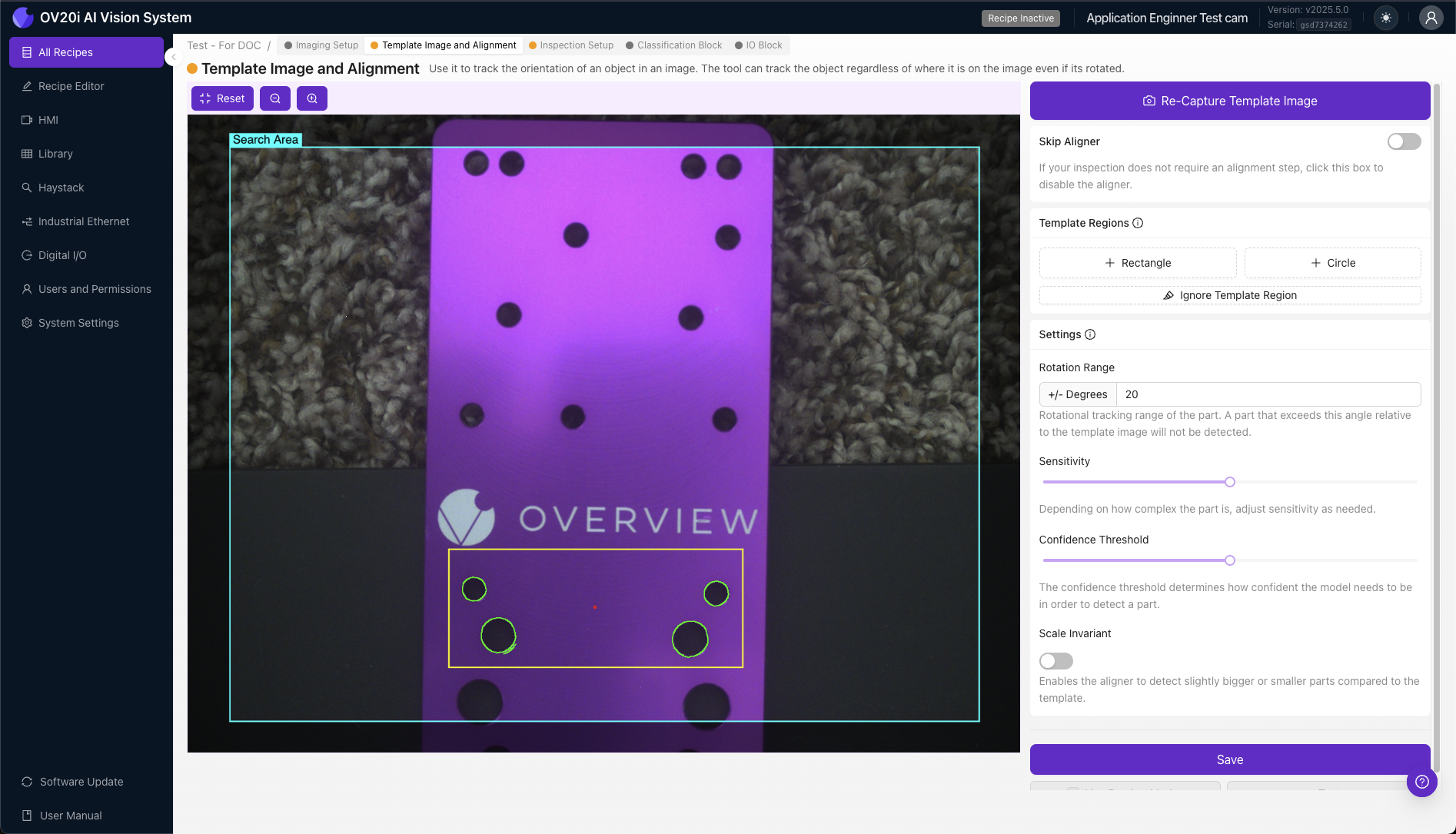
- Re-Capture Template Image - Replace existing template with new image
- Import From Library - Select existing image from Library as template
By default, the Import From Library modal will filter images by Recipe. Use the drop-down menu to select another recipe or clear the filter and click Search to find images from other Recipes.
Preview Modes
- Template View - Once captured, preview pane displays the Template Image (not live camera)
- Live Preview Mode - Switch to real-time camera view to test alignment performance
- Re-capture Mode - Disable live preview to retake Template Image
Edge Detection for Alignment Theory
Alignment-Specific Edge Detection
The OV20i alignment system relies on edge detection algorithms specifically for part location and orientation, separate from AI-based inspection models.
Alignment Edge Detection Process:
- Edge Identification - Algorithm detects intensity gradients for alignment reference
- Edge Filtering - System identifies alignment-relevant edges while filtering noise
- Alignment Pattern Creation - Builds mathematical representation of edge pattern for positioning
- Position Comparison - Compares detected patterns against template reference for alignment
Alignment Region Strategy
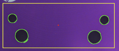
+ Rectangle / + Circle Regions: Template Regions define specific areas where the OV20i will detect edges for alignment purposes, matching similar edge patterns to determine part position and orientation.
Alignment Edge Visualization:
- 🟢 Green Highlights - Edges found inside Template Region (suitable for alignment)
- 🔴 Red Highlights - Insufficient edges found for valid alignment
Edge Quality for Alignment
Good Alignment Edge Characteristics:
- Simple - Clear, well-defined edge transitions suitable for position reference
- Unique - Distinctive patterns for reliable part identification
- Consistent - Visible across all expected part variations for reliable alignment
- Stable - Not affected by normal production variations during alignment
Poor Alignment Edge Characteristics:
- Complex Textures - Detailed surfaces unsuitable for position reference
- Reflective Surfaces - Areas creating inconsistent alignment references
- Variable Features - Elements that change between parts, affecting alignment consistency
- Noise-Prone Areas - Regions with debris affecting alignment accuracy
Template Regions Management
Creating Template Regions
+ Rectangle / + Circle: Click to add a Template Region to the Template Image. The OV20i will detect edges inside these Template Regions and try to locate parts by matching similar edge patterns.
Region Management:
- Resize/Reshape - Click on Template Region to stretch or change size
- Rotate - Adjust region orientation as needed
- Reposition - Click and drag to move Template Region
- Delete - Remove unwanted regions
Template Region Placement Best Practices
When placing Template Regions, focus on edges that are simple, unique, and consistently visible across all parts. Try to avoid edges that may be obscured by defects, or edge patterns that vary from part to part.
Good Edge Characteristics:
- ✅ Simple - Clear, well-defined edges
- ✅ Unique - Distinctive patterns not found elsewhere
- ✅ Consistent - Visible across all part variations
- ✅ Stable - Not affected by normal defects or wear
Poor Edge Characteristics:
- ❌ Variable features - Components that may be missing or damaged
- ❌ Textured surfaces - Complex patterns that vary part-to-part
- ❌ Reflective areas - Surfaces that create variable highlights
- ❌ Small details - Features easily obscured by debris
Progressive Setup Approach
Multiple Template Regions Strategy:
- Start with one Template Region on most prominent feature
- Add additional regions if edge count is insufficient (red highlights)
- Increase sensitivity if needed to find adequate edges
- Use Ignore Template Region tool to remove noise
- Test with Live Preview Mode across part variations
Alignment Parameter Theory
Rotation Range Tolerance
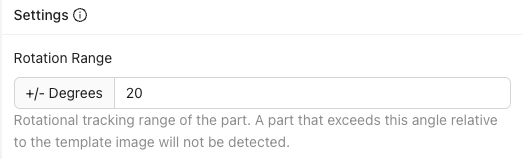
Enter an angle of 0-180 degrees to define the amount of rotation the aligner will tolerate.
Rotation Range Settings:
- 180 degrees - Find parts rotated at any angle (maximum flexibility)
- 0 degrees - Find only parts that match Template Image angle (maximum precision)
- Custom range - Balance between flexibility and precision
Trade-offs:
- Wider range - More flexible but potentially slower processing
- Narrower range - Faster processing but requires consistent part orientation
Sensitivity Algorithm Theory
Adjust the slider to increase/decrease edge-finding sensitivity. Higher sensitivity settings will find more edges, and lower sensitivity settings will find fewer edges.
Sensitivity Impact:
- Higher Sensitivity - Detects more edge details but may include noise
- Lower Sensitivity - Focuses on prominent edges but may miss subtle features
- Optimal Setting - Lowest sensitivity that still finds adequate edges

Algorithm Behavior: The alignment edge detection algorithm adjusts its threshold based on sensitivity settings, affecting which intensity gradients are classified as edges for alignment purposes.
Confidence Threshold Theory
Use this slider to set the minimum confidence required for an Alignment to be considered valid (1% indicates an identical match). This threshold should fall between 0.6-0.9 for consistent alignment.
Confidence Calculation:
- Alignment Pattern Correlation - Mathematical similarity between template and detected alignment patterns
- Geometric Consistency - Spatial relationship accuracy between edge features for positioning
- Alignment Edge Quality - Strength and clarity of detected edge patterns for position reference
Threshold Guidelines:
- 0.6-0.9 Range - Recommended for consistent alignment performance
- Higher Values - More strict matching, reduces false positives
- Lower Values - More lenient matching, may accept poor alignments

Alignment Noise Management Theory
Ignore Template Region for Alignment
The Ignore Template Region tool provides a brush interface to erase unwanted edges from any Template Region, used to mask out unwanted edge noise and focus alignment on clear, repeatable edge patterns.
Alignment Edge Noise Categories:
- Textured Surfaces - Complex patterns unsuitable for consistent alignment reference
- Reflections and Glare - Variable lighting effects that affect alignment accuracy
- Debris or Contamination - Temporary features not suitable for position reference
- Variable Components - Features that may be missing or damaged, affecting alignment consistency
Alignment Noise Filtering Strategy:
- Selective Masking - Remove variable edge patterns while preserving stable alignment features
- Pattern Simplification - Focus alignment algorithm on most reliable edge information
- Consistency Optimization - Improve alignment reliability across part variations
Alignment Pattern Matching Performance Theory
Multiple Template Regions for Alignment
Adding more Template Regions increases the number of edges for Alignment, improving both reliability and specificity of alignment pattern matching.
Multi-Region Alignment Benefits:
- Alignment Redundancy - Multiple reference points improve alignment robustness
- Position Specificity - More complex patterns reduce false positive alignment matches
- Alignment Accuracy - Additional constraints improve position and rotation precision
- Alignment Reliability - System can still align if some regions are obscured
Alignment Failure Modes
Common Alignment Failure Patterns:
- Insufficient Alignment Edges - Not enough pattern information for reliable position detection
- False Alignment Positives - Algorithm matches incorrect features for positioning
- Inconsistent Alignment Detection - Alignment works on some parts but fails on others
- Low Alignment Confidence - Position match below acceptable threshold
Alignment Optimization Solutions:
- Alignment Pattern Optimization - Choose more distinctive and stable edge features for positioning
- Region Adjustment - Modify Template Region size and placement for better alignment reference
- Parameter Tuning - Adjust sensitivity and confidence thresholds for alignment performance
- Alignment Noise Reduction - Use Ignore Template Region tool to filter problematic edges
Alignment vs Fixed Positioning Theory
When to Use Template Alignment
Alignment Advantages:
- Part Variation Tolerance - Accommodates position and rotation differences
- Flexible Presentation - Works with non-fixtured parts
- Relative Inspection - ROIs automatically adjust to part position
- Robotic Integration - Handles variable part placement
When to Skip Alignment
Fixed Position Advantages:
- Processing Speed - No alignment computation required
- Consistent Results - Predictable inspection behavior
- Simple Setup - No template regions or pattern matching needed
- Reliable for Fixtured Parts - When mechanical positioning ensures consistency
Selection Criteria: Skip Aligner option recommended for applications with parts that are fixtured or presented to the camera very repeatably.